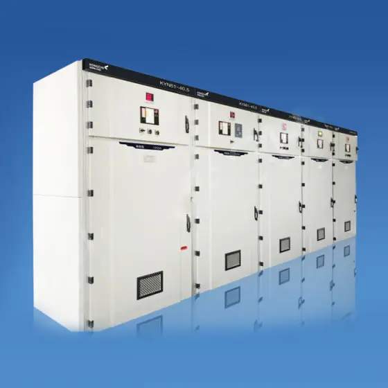

What Is Draw-Out Switchgear and How Does It Work?
What Is Draw-Out Switchgear and How Does It Work? is one of the first questions a procurement engineer asks when a low-voltage distribution upgrade is moving from concept to purchase order. Picture this: a plant has a shutdown window of only six hours, the maintenance team needs to test one feeder breaker, and the production line cannot lose power to every other circuit. Fixed switchgear can force a broader outage; draw-out switchgear changes the maintenance plan because the breaker sits on a carriage, rolls into a dedicated compartment, and can be moved to a test or disconnected position without disturbing the main busbars. In simple terms, draw-out switchgear is a modular low-voltage distribution assembly in which the circuit breaker is removable, mechanically guided, and protected by compartment shutters and interlocks. Buyers value it because it supports faster replacement, safer isolation, clearer fault tracing, and better lifecycle planning. Raydafon Technology Group Co., Limited builds draw-out switchgear for projects that need that balance of uptime, safety, and procurement confidence. This guide explains the working principle, the parameters to verify, the scenarios where draw-out design pays back, and the questions to ask before you approve a supplier.
Jump to the section you need:
- Why draw-out switchgear matters in real procurement scenarios
- How draw-out switchgear works in daily operations
- Which parameters buyers should confirm before ordering
- How to compare draw-out and fixed switchgear
- Safety and maintenance checks that protect uptime
- Two quick Q&A groups for busy buyers
- Where Raydafon Technology Group Co., Limited fits your shortlist
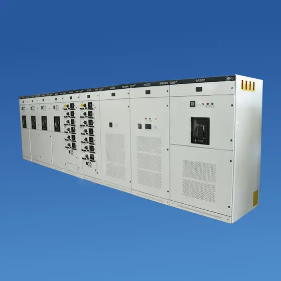
Why Draw-Out Switchgear Matters in Real Procurement Scenarios
A maintenance manager at a food-processing plant receives an audit finding: the main low-voltage panel cannot isolate one critical feeder for breaker replacement without shutting down the main busbar. Production wants a Saturday maintenance window, the electrical contractor wants a clear isolation point, and the procurement team wants a solution that will not turn into a custom engineering headache. The pain is not only downtime; it is the risk of unplanned production loss, extended safety permits, and repeated manual intervention during fault tracing.
The practical solution is a draw-out design with compartmented breaker cells, clear position indicators, and mechanical interlocks that guide the operator through a safe sequence. Raydafon Technology Group Co., Limited supports this by matching feeder criticality, breaker frame sizes, cable entry, and future expansion space before the panel is released for production. The result is a switchgear lineup that lets one feeder be isolated for service while the rest of the board continues to supply the plant.
Table 1: Fixed versus draw-out switchgear from a procurement view
| Decision point | Fixed switchgear | Draw-out switchgear | Procurement impact |
|---|---|---|---|
| Breaker removal | Requires busbar isolation or major disassembly | Breaker rolls out on a carriage | Faster spare replacement and less downtime |
| Maintenance outage | Often affects a wider section | Single compartment can be isolated | Better production continuity |
| Operator safety | More exposed work near live parts | Shutters and interlocks separate live terminals | Stronger audit and permit-to-work story |
| Footprint | Compact for simple projects | Larger due to compartments and carriage space | Plan room early to avoid site rework |
| Initial cost | Lower for basic panels | Higher component and engineering content | Compare against lifecycle downtime cost |
| Best fit | Small, stable, low-maintenance loads | Critical feeders, frequent testing, phased expansion | Align design with uptime targets |
How Draw-Out Switchgear Works in Daily Operations
A new operator stands in front of a low-voltage board and sees a breaker handle, a position indicator, and a set of shutters. Without a clear sequence, the risk of forced operation, incomplete isolation, or a damaged contact cluster rises. The pain appears as inconsistent switching, unnecessary callouts, and slow fault recovery during a shift change.
The solution is a mechanical sequence that is easy to teach. The breaker is racked on a guide rail, the primary contacts are shielded by shutters, and the interlock prevents the breaker from being moved unless it is in the correct state. In everyday language, What Is Draw-Out Switchgear and How Does It Work? comes down to four positions: connected for normal service, test for control checks with main circuits isolated, disconnected for safe removal, and withdrawn for bench work or replacement. Raydafon Technology Group Co., Limited labels these positions clearly and provides operation and maintenance drawings so the site team can follow the same procedure every time.
Table 2: Breaker positions and what they mean on site
| Position | Primary contacts | Control circuit | Typical action |
|---|---|---|---|
| Connected | Engaged with main busbar and feeder | Available | Normal power distribution and protection |
| Test | Isolated, shutters closed | Available for testing | Trip checks, secondary injection, interlock verification |
| Disconnected | Isolated, breaker still in cell | Usually isolated | Safe local inspection before removal |
| Withdrawn | Breaker removed from cell | Isolated | Replacement, bench service, contact inspection |
Which Parameters Should Buyers Confirm Before Ordering Draw-Out Switchgear?
A buyer sends a one-line diagram and asks for a quotation, but the returned offer mixes fixed and draw-out sections, omits the short-time withstand current, and leaves the cable entry direction unclear. The pain shows up later as drawing revisions, delayed approval, and site arguments about space and access. For procurement teams, a vague specification is not a shortcut; it is a hidden change-order risk.
The solution is to confirm the electrical and mechanical parameters in one review meeting before production. Raydafon Technology Group Co., Limited reviews the single-line diagram, breaker schedule, fault level, environmental conditions, and future expansion plan, then returns a marked-up datasheet and general arrangement drawing. This gives the buyer a clear basis for technical comparison, not just a price comparison.
Table 3: Typical parameters to verify for low-voltage draw-out switchgear
| Parameter | Typical range or option | Why it matters |
|---|---|---|
| Rated operational voltage | 400 V, 415 V, 690 V | Must match plant distribution and equipment rating |
| Insulation voltage | 690 V to 1000 V class dependent | Supports creepage and clearance review |
| Frequency | 50 Hz or 60 Hz | Affects protection settings and component selection |
| Main busbar current | 630 A to 6300 A and above | Defines future load growth and thermal margin |
| Short-time withstand current | 50 kA, 65 kA, 80 kA or project-specific | Critical for fault level coordination and safety |
| Breaker type | ACB or MCCB draw-out units | Affects compartment size, carriage, and spares strategy |
| Enclosure protection | IP31 to IP54, project dependent | Relates to dust, humidity, and cleaning routine |
| Compartments | Breaker, busbar, cable, auxiliary | Improves isolation and maintenance access |
| Interlocks | Mechanical and key interlock options | Reduces misoperation risk during switching |
| Compliance evidence | IEC 61439 design verification and test reports | Supports tender review and site acceptance |
How to Compare Draw-Out and Fixed Switchgear for Your Project
A project team is under budget pressure and asks whether fixed switchgear can do the same job. The pain is real: the initial price is lower, but the operations team knows that a single breaker failure could stop a critical process. If the comparison is based only on first cost, the later downtime cost, spare-part logistics, and safety controls are invisible in the decision.
The solution is to score the design against the operating scenario, not only the bill of materials. Raydafon Technology Group Co., Limited helps buyers compare uptime targets, maintenance frequency, fault level, expansion plans, and available floor space. For critical feeders, a draw-out solution often pays back through faster isolation and cleaner spare management; for simple, stable loads, a fixed design can still be the right choice.
Table 4: Selection matrix for common project scenarios
| Project scenario | Recommended direction | Reason | Parameters to watch |
|---|---|---|---|
| Data center or server room | Draw-out for critical feeders | Fast service and predictable spare swap | Fault level, selective coordination, heat rise |
| Hospital or laboratory | Draw-out on essential circuits | Maintenance without wide shutdown | Test position, interlocks, alarm contacts |
| Manufacturing line | Mixed design by feeder criticality | Balances budget and uptime | Breaker frame, cable access, expansion space |
| Water treatment plant | Draw-out for remote or hard-to-access sites | Reduces site work during repair | IP rating, corrosion protection, spare parts |
| Commercial building | Fixed or draw-out based on load profile | Simple loads may not justify full draw-out | Footprint, initial cost, maintenance contract |
| Renewable energy support | Draw-out for main incomers and critical feeders | Supports phased expansion and service access | Short-circuit withstand, ambient temperature |
Safety and Maintenance Checks That Protect Draw-Out Switchgear Uptime
Dust builds up in a cable compartment, a busbar joint warms under load, and an interlock feels stiff after months of infrequent operation. None of these conditions looks dramatic during a walk-through, but together they create the kind of pain that appears as a sudden trip, a hot spot, or a failed racking operation during a critical maintenance window.
The solution is a simple, repeatable inspection routine that matches the site environment. Raydafon Technology Group Co., Limited recommends checking the breaker position sequence, shutter operation, interlock function, contact condition, torque marks, and thermal performance during planned outages. Infrared thermography and partial discharge screening can be added where criticality is high. The goal is not to create paperwork; it is to catch small deviations before they become production losses.
Table 5: Practical maintenance checklist for draw-out switchgear
| Check | Frequency | What good looks like | Risk if missed |
|---|---|---|---|
| Visual inspection of compartments | Monthly or site routine | No dust, moisture, smell, or discoloration | Insulation degradation and tracking |
| Interlock and shutter operation | Before each racking campaign | Smooth movement, clear position indication | Misoperation and unsafe isolation |
| Breaker exercise | Planned maintenance interval | Clean close and trip, no abnormal sound | Sticking mechanism and slow response |
| Torque and connection check | During shutdown | Marked fasteners remain aligned | Hot joints and thermal damage |
| Infrared thermography | Under load, planned interval | Balanced temperature across phases | Hidden hot spot and fire risk |
| Partial discharge screening | Critical boards or after fault | No rising trend above baseline | Insulation failure without warning |
Two Quick Q&A Groups for Busy Buyers
Q1: Is draw-out switchgear the same as withdrawable switchgear?
Yes, in most procurement discussions, draw-out switchgear and withdrawable switchgear describe the same concept: the circuit breaker is mounted on a removable carriage and can be moved between connected, test, and disconnected positions. The important difference is not the name; it is whether the supplier provides clear compartment separation, reliable shutters, proven interlocks, and documentation that matches the delivered assembly. Raydafon Technology Group Co., Limited uses the terms consistently in drawings and quotations so buyers can compare offers without confusion.
Q2: Can a draw-out breaker be replaced without shutting down the main busbar?
In a correctly designed draw-out assembly, the individual breaker can be isolated and removed while the main busbar remains energized. That does not mean the work is risk-free; the site must follow lockout, permit-to-work, and verification procedures, and the compartment must be rated for the intended isolation method. The procurement lesson is to confirm the position sequence, shutter design, and interlock logic before approval, because these details decide whether the maintenance team can actually use the draw-out feature in service.
Table 6: Buyer answer summary
| Question | Short answer | Procurement action |
|---|---|---|
| Draw-out versus withdrawable? | Same functional concept | Check terminology in the datasheet and drawings |
| Replace one breaker without main busbar shutdown? | Possible with correct compartment and isolation design | Verify interlocks, shutters, and site switching procedure |
Where Raydafon Technology Group Co., Limited Fits Your Shortlist
A buyer has three quotations, two similar prices, and very different levels of technical clarity. The pain is not finding a panel builder; it is finding a supplier that can answer the application questions, provide drawings that match the site, and stay responsive after the purchase order. Weak documentation creates delays at approval, at site delivery, and during the first maintenance window.
The solution is to work with a supplier that treats engineering support as part of the product. Raydafon Technology Group Co., Limited can review your single-line diagram, propose a draw-out configuration by feeder criticality, prepare general arrangement drawings, and coordinate the documentation package for tender and site acceptance. Whether your project needs a low-voltage draw-out switchgear lineup, a mixed fixed and draw-out design, or a replacement section for an existing board, the goal is the same: reduce technical uncertainty before the equipment leaves the factory.
Table 7: Support points that matter to procurement teams
| Support area | What Raydafon Technology Group Co., Limited provides | Buyer benefit |
|---|---|---|
| Application review | Feeder criticality, fault level, and space check | Fewer drawing revisions |
| Technical documentation | Datasheets, drawings, and test evidence coordination | Faster tender and approval review |
| Configuration | Draw-out, fixed, or mixed sections by project need | Budget and uptime balanced together |
| Production control | Factory assembly and routine verification | Consistent delivery quality |
| Packing and logistics | Export packing and shipping coordination | Less site damage and delay |
| After-sales response | Spare-part and technical support contact | Better lifecycle continuity |
If your next project includes critical feeders, limited shutdown windows, or a tender review that demands clear safety evidence, bring your single-line diagram, breaker schedule, and site constraints to the discussion early. A short technical review can reveal whether draw-out switchgear is the right fit, where a fixed section can save budget, and which parameters must be fixed before quotation. Send your project details and let the Raydafon team help you turn the specification into a practical, reviewable package.
Raydafon Technology Group Co., Limited is an electrical equipment supplier focused on low-voltage switchgear, draw-out switchgear, and project-based power distribution solutions. The company supports procurement teams, consultants, and contractors with application review, configuration advice, documentation coordination, and export-ready delivery. Visit https://www.raydafonequipments.com to learn more about the product range, or email [email protected] with your single-line diagram, target schedule, and technical requirements for a focused response.
Research references for further reading
M. Kezunovic, Z. Ren, G. Latisko, D. R. Sevcik, J. Lucey, W. Cook, and E. Koch (2006). Automated monitoring and analysis of circuit breaker operation. IEEE Transactions on Power Delivery, 21(4).
A. A. Razi-Kazemi, M. Vakilian, K. Niayesh, and M. Lehtonen (2013). Circuit breaker condition assessment based on trip coil current signature. IEEE Transactions on Power Delivery, 28(3).
J. C. Das (2005). Arc flash hazard analysis and mitigation. IEEE Transactions on Industry Applications, 41(6).
G. C. Stone (2005). Partial discharge diagnostics and electrical equipment insulation condition assessment. IEEE Transactions on Dielectrics and Electrical Insulation, 12(5).
R. L. Doughty, T. E. Neal, and H. L. Floyd (2000). The use of low-voltage circuit breakers for arc flash protection. IEEE Transactions on Industry Applications, 36(3).
M. E. Valdes, D. L. Swindler, and J. P. Gosalia (2014). Arc flash protection for low-voltage systems: practical coordination considerations. IEEE Industry Applications Magazine, 20(3).
G. C. Montanari, A. Cavallini, and F. Ciani (2013). Partial discharge monitoring of switchgear: from diagnostics to prognostics. IEEE Electrical Insulation Magazine, 29(4).
Y. Zhang, J. Wang, and H. Li (2020). Thermal condition monitoring of low-voltage switchgear based on infrared thermography. IEEE Transactions on Instrumentation and Measurement, 69(9).
A. A. Razi-Kazemi and K. Niayesh (2016). Online monitoring of high-voltage circuit breakers using vibration analysis. IEEE Transactions on Power Delivery, 31(2).
H. Wang, Y. Liu, and L. Zhou (2018). Fiber Bragg grating sensors for temperature monitoring in low-voltage switchgear. IEEE Sensors Journal, 18(12).
Next:
-
Related News
- What is fixed switchgear and how does it work?
- What factors affect the price of branded LV switchgear?
- What are the standard dimensions of a prefabricated substation?
- How do you maintain an air-cooling ESS cabinet?
- What are the key components of a liquid-cooling ESS cabinet?
- What are the main components of a YBM prefabricated substation?
Leave me a message
New Products
News Recommendations